What happened to my Amiga?
I've had my Amiga 1200 for may years. Over time it has gathered quite a few expansions.
On this page I try to sort out what all of it is and how it ended up in my computer.
Once upon a time there was a computer...
One day I was installing a new network card into my Amiga 1200. While
sitting there, fighting all the cables and stuff to gain access to the PCMCIA port
I started thinking of all the hacks and mods this poor computer has been through
over the years. It's hard to visualize today, but once upon a time this was a
clean desktop A1200 without any extensions. How did this innocent machine turn into
this tower monster filled with cable mess and circuit boards without me noticing it?
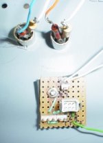
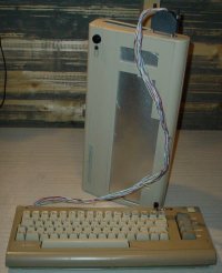
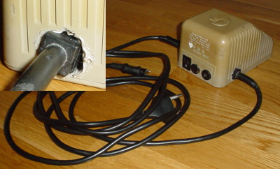
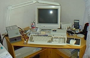 This is what the computer looked like once. When this picture was taken the Amiga had already started to grow. Some hardware sits next to the computer and on the top there are a few switches that tells a tale about home made hacks. |
|
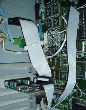
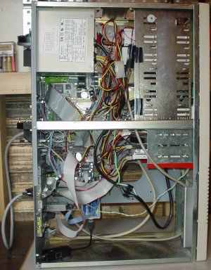 This is what I see when removing the cover... |
|
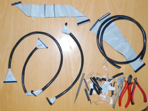
In a desperate attempt to sort out all the cables and improve the air flow in the computer
(or at least enable some air flow) I decided to get to the bottom of this. I cleaned out
all the cables and cards from the box.
This is the story about how the pile of parts became a computer again.
Warning!
Don't do this at home! Your Amiga will burn and it will cost you a fortune to repair it.

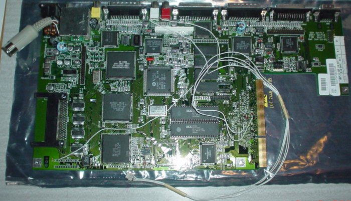
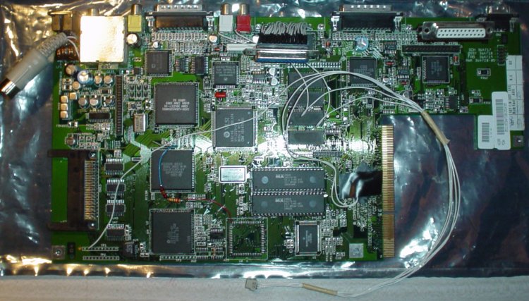
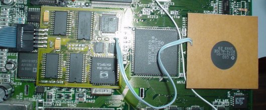
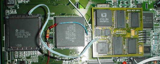
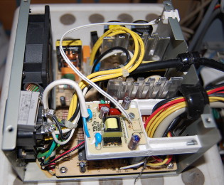
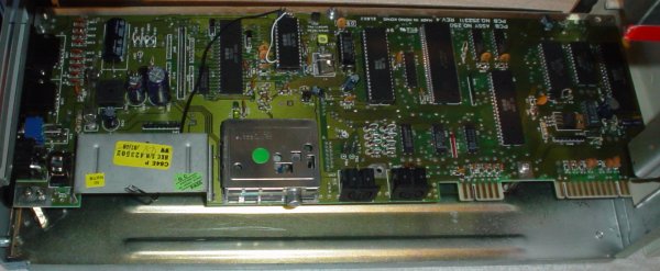
A motherboard
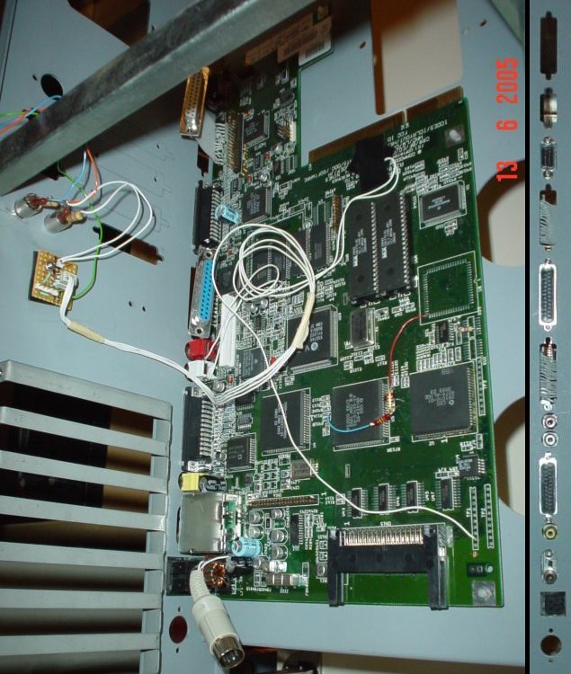
The picture above shows the motherboard in the Amiga 1200. This one is a Commodore made Rev 1D.4.
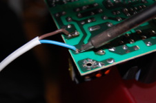
I did my best to clean it from hacks but there are a few that I couldn't remove without soldering
(and I didn't want to do that). These are the white wires in the picture and the connector in the
upper left corner.
|
|
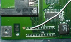
The first of the white wires is connected to /KBRESET among the test pads on the lower left of the
motherboard. The other end of this wire will take us to the reset button in the tower case.
|

|
|
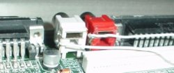
The next two wires are connected to the right and left audio channels and are used for a mono/stereo switch.
|
|
|
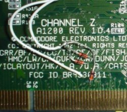
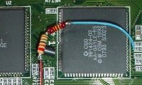
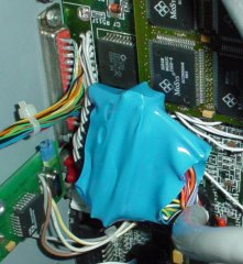
In one end of wire number four there are three diodes that are connected to the Amiga interrupts signals.
The other end will have a button to generate level 7 interrupts. To protect the diodes from shortage i put
some insulation tape around them.
The fifth wire connects to the /HLT signal and will be used for a pause button. All five wires are
gathered in a connector. This makes it possible to disconnect the motherboard without having to
remove all switches and stuff. Very hand a day like this.
|
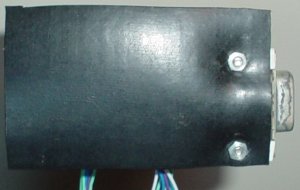
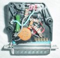
The next hack on the motherboard is the power connector. I don't want to bring a cable from the internal
PSU out of the box just to plug it back in to the computer. An internal power connector on the motherboard
is therefore required. In theory I could attach the wires directly from the PSU to the motherboard, but
for the same reason as I used a connector above I'll use one here as well. It can be any kind of connector
with five pins, this one happened to be from an old keyboard.
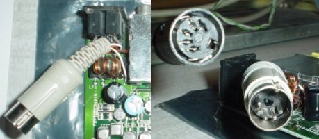 Internal power connector on the motherboard. The female brings power from the internal PSU. |
|
|
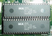
I wouldn't call this a hack but rather an upgrade: The ROM in this Amiga was originally v3.0,
now I have v3.1 in there.
|
When I'm at it
As I have the motherboard easily accessible there are a few things I want to fix. The first
is to patch Gayle so that the reset signal is sent to the PCMCIA port.
|
 Gayle with a patch. |
|
That has to go...
The next hack is in line with the internal power connector but it will be some more work. I don't
like it when cables are brought out of an Amiga tower just to make a U-turn and connect back into
the computer. The power coord is a classic, the external disk drive connector is another. I've
already done the power coord but there are two more that I want to get rid of.
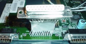
The first one is the parallel port. I have an internal parallel port splitter and to connect it on
the inside of the Amiga I need an internal parallel port. This may sound cruel but the parallel port
needs to go. However, that turned out to be easier said than done.
... and that one to
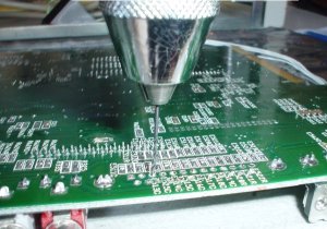
The next port to face the same destiny is the external disk drive port. That one actually caved to the
solder extractor and was easy to remove. A new port is put in place.
 A new disk drive port in place. |
|
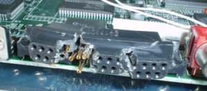 After having tried both solder extractor and desoldering braid I had to use drastic methods to get rid of the parallel port. |
 Finally gone. |
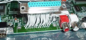 New internal port in place. |
|
Now the motherboard has had enough for today. Time to have a look at the case.
A case
|
|
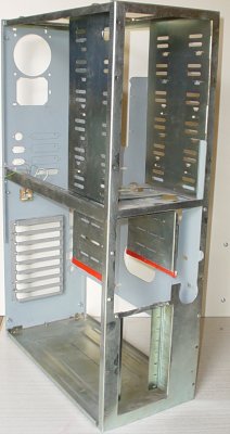
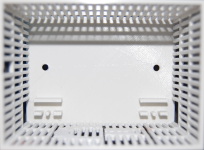
This is an old Eagle case that I bought around -96. It was prepared for the A1200 so I didn't
have to make any modifications to it. Well, almost none.
|
It's a fairly big case which is good considering what I have planned for it (you've seen nothing yet).
There is room for six 5,25" units and three 3,5" units. Previously I had to cut out a piece of the
plane used to attach the motherboard since it was in the way for the heatsink on a 040 expansion card
I used for a few years.
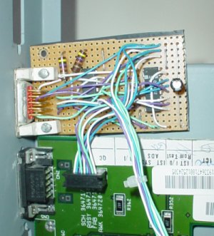
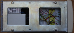
 Old hacks. |
|
In the picture we can see a few small hacks that I couldn't remove without soldering. There are
two new audio ports that I will come back to later, and a small circuit where the connector from
the motherboard will be connected. The circuit also have pins to connect the reset button, a
pause button, the level 7 interrupt button, and a switch to change between mono and stereo sound.
|
|
|
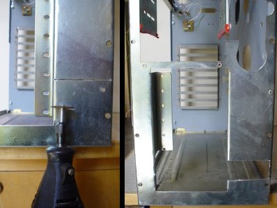 I cut a hole to make room for my new project. I will need some brackets and other stuff as well, but we'll get there later. |
|
To make room for the extras that I want to fit into the tower I need to make another
cut with the Dremel.
There is obviously a front and a cover for this case as well, but we don't need those just yet.
|
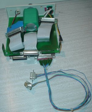
The motherboard and it's closest expansions
It's time to put back the motherboard into the case. I plug in the small connector from the
motherboard into the circuit already in the case. This will later continue on to buttons on the
front of the computer. I'll now start installing the expansions that are closest to the motherboard.
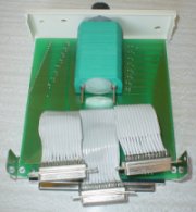
 On the right we see the connectors that are currently available on the back of the computer. |
Keyboard interface
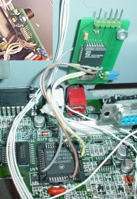 Keyboard interface installed. In the upper left corner we see the spacer that I used behind the circuit board. |
|
The first extension I add is the keyboard interface. It's manufactured by DCE and originally the socket
was attached to the bottom of the circuit board so that the entire interface was placed on the motherboard.
Eventually it got too crowded down there though so I had to remove the socket and move the circuit board
to the side. At first I had slightly longer wires between the interface and the socket but that caused
problems with the keyboard. The current length has worked fine for many years now. Between the circuit
board and the case there is a small plastic spacer to avoid short circuit.
|
The keyboard connector that came with the interface was not made for tower cases, who would ever want such
a connector is beyond me. I cut it off and used it for the power supply instead. A new, more aesthetic
keyboard connector is now in place. Pin 5 (Vcc) is connected directly to the power supply. The keyboard
interface did not provide enough current for external equipment that uses this connector to get power.
|
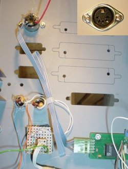 The new keyboard connector installed. The connector as seen from the outside is shown in the upper right corner. |
|
|
 Again, the new keyboard connector installed. |
|
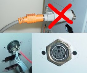
Update 2005-07-28:
You'd think it would stay there, however when I bought a new keyboard it came with a mini-DIN connector instead of the
old, bigger one. Using an adapter behind the computer is not my style so I had to replace the connector.
Update 2017-08-06:
The keyboard connector has now been moved again... More about that later.
|
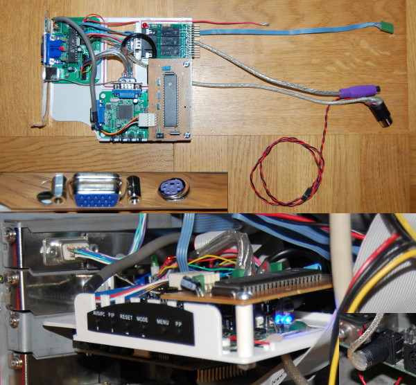
Scandoubler / Flickerfixer
This scandoubler is called Scanmagic/FF and from that name you already guessed that is has a builtin
flickerfixer. It clips on to Lisa and Alice using empty sockets. The scandoubler was the reason the
keyboard interface couldn't stay on the motherboard, the circuit boards collided as Lisa and the keyboard
MPU is located close to each other. With the new patch on Gayle there is even less space down there
and the circuit board that is supposed to be located on top of Alice can't fit any more.
On the circuit board in question there is actually nothing more than the socket that clips on to Alice,
and only two pins on Alice is connected. Using hot air and a sharp knife I remove the socket from the
board in the same way I did on the keyboard interface. I solder the wires directly onto the socket
and suddenly there is much more space down there. The scandoubler obviously have a connector for the
video output, but I'll hold on to that one a while more.
Processor, memory and graphics
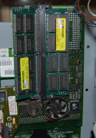
An accelerator is more or less a necessity if the Amiga is to be used for anything interesting these days.
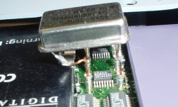
In this Amiga I have a BlizzardPPC 603e+. It has a 240MHz PPC processor and the 060 is overclocked from
the standard 50MHz to 64MHz. I put the crystal in a socket to make it easy to change it. However, the 64MHz
crystal I found was not square as the original was, so I had to add some extra legs to the crystal and bend them
to fit into the square socket. The Blizzard card is also equiped with a SCSI-II controller, 64MB RAM, and a
BVision graphics card.
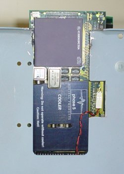
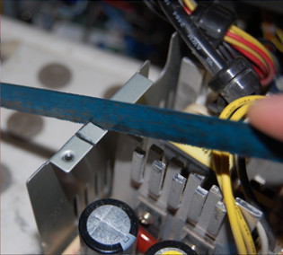
In order for the BPPC card to get enough power one should connect an extra power cable to the motherboard using
the floppy power connector. On the BPPC card there is also a connector for the CPU fan that can be used to provide
some extra power to the card. To get to this connector later, I need to remove another pice of the metal backplane.
Bring out the saw!
|
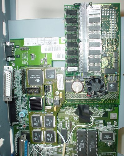
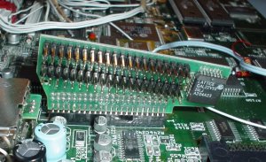
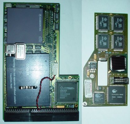 Blizzard PPC 603e+ and BVision. |
|
|
The BPPC installed. To the right we see the card from the back. Here we can see the new cut in the metal to access the power connector (so far the fan is still connected here). Slightly above the cut we can see the old cut that was made to fit a cooler on the old 040 board. At the top right we see a closeup of the new, larger crystal. Note the bent legs. |
|
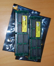
Update 2015-02-23:
When going through a box of old memories it is easy to feel both happy and nostalgic. You get extra happy when you
find two 128MB SIMMs that you bought a long time ago but never installed. 64MB is not too little memory in an Amiga
really, but I can't just leave these memory circuits uninstalled. Time to open the case again!
|
|
Mouse or joystick? Why not both?!
Two ports activated by the respective fire button (or left mouse button). The bottom half of the picture shows the bottom of the circuit with the rubber mat. |
|
You've probably noticed that I didn't connect the mouse port yet. On the Amiga 1200 rev 1D.4 the mouse port is
not placed on the motherboard but is connected through a flat cable. I have chosen to build an automatic
joystick switch to place here instead of the original port. The reason for this is that it is too much of
a hassle to get behind the computer in order to change between the mouse and a joystick.
The circuit is screwed to the case through the mouse port. The second port will end up further down in the
case since there is no prepared hole for a 9-pin Dsub up here. I'll get back to this second port later.
To protect the card from shortages I've added a rubber mat beneath it.
 Now we can connect the mouse as well :). |
|
IDE port extension
 EIDE'99 is a buffered IDE interface. |
|
You won't get far with a single IDE port. Fortunately the built-in IDE port on the Amiga is already prepared
to handle up to four devices, the only thing needed is a suitable cable. I used to have a cable that
I made out of the original IDE cable from the A1200 and two standard IDE cables. I basically just soldered the
wires together and had protective insulation tape to keep the wires apart. This worked quite good but it didn't
look very nice, so in the end I bought an EIDE'99 which has the bonus of being a buffered interface.
On the EIDE'99 there are two connectors for standard IDE cables which I intend to connect. I will do that later
though since I have a few more things to put in the box and the IDE cables are one of those things that tend to
consume a lot of space.
|
Serial port extension
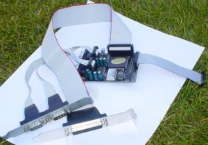 Hypercom 3+. If the weather allows even computer geeks can be outside ;). |
|
For a while there was a lack of serial ports in my Amiga. To get away from having to switch cables all the time
and to improve the transfer rate I bought a Hypercom 3+. This card has two serial ports and a parallel port.
The Hypercom 3+ attaches to the clock port using a flat cable, also the parallel port is connected using
a flat cable. The serial port offers two possibilities, either you can use the two ports that are mounted directly
on the circuit board, or you can attach them using two flat cables. As you figured out by now this has the potential
of adding a lot of cables.
The clock port cable that came with the Hypercom was too short to allow me to place the card in one of the card
slots in the Eagle case which originally gave me no option but to attach the serial ports using the cables and
leave the card itself hanging in mid air in the case. This may sound worse than it actually was. The card was
embedded in flat cables so there was no risk for shortages or any other damage, but it sure didn't look good.
|
|
My goal now is to get rid of as many cables as possible to allow some air flow, and I really don't want to have
the card hanging in the air. The best way to get order here was to make a longer cable to the clock port. The
cable was slightly more modern than anything I had at home at the time with just 1 mm between the wires, so
that I had to buy. With the new cable in place I could place the card in one on the slots in the case and get
rid of the serial port cables.
|
 Now I use the two built in serial ports. Higher up in the picture we see the parallel port and the cable for the clock port takes of to the right. |
|
Joining video ports
|
|
As I have both a scandoubler and a graphics card I'm dealing with two video ports, one for applications with CGX
support, and one for AGA and classic resolutions. I can't fit another monitor on my desk and moving the video cable
back and forth is not sustainable. A BMon monitor switch solves this problem.
The switch joins the two video ports into one. I place the BMon in one of the card slots and connects the cables to
the graphics card and the scandoubler. Another small cable is connected and brought to the front of the case where
the button will be to switch between the two screens.
In the picture the grey BMon is seen at the bottom. The black cable is connected to the BVision in the upper part
of the picture. The scandoubler is located next to BMon and is connected with the light blue cable.
BMon cones with a manual switch to select video output. I intend to use the turbo button that already exists in the
case so I remove the switch. The switch was connected to a small circuit board that I place in the top of the tower
case, since that is where the turbo button is, and connect the turbo button instead.
Update 2017-08-06:
A major change in the video handling in this computer has been made and the BMon was moved to a different location.
More about that later.
|
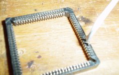
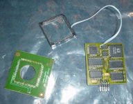
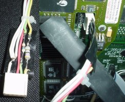
Network
|
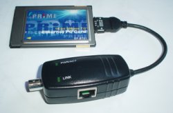
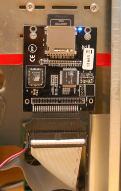
In the PCMCIA port I'll install a network card. It is a 10 Mbit card branded Prime. Since we are down at the
bottom of the tower here a 90 degree angel is required for the PCMCIA port to make the card fit into the Amiga.
The adapter that came with the card has connectors for TP and coaxial. I want both of these accessible
to connect to whatever network is available. The connectors should obviously be placed on the back of the computer
and the best place would be in one of the card slots. The connectors in the adapter however are not suitable for
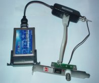
card slot installation so I'll go with a slightly ugly hack here. I take an old network card that already have the required
connectors neatly placed and ready to install in the card slot. Since I'm only interested in the connectors I'll
cut the network card directly after them, giving me a small circuit board attached to the metal plate. Now I
attach the wires from a TP cable and a coax cable directly to the connectors. The other end of both cables has
the proper connectors in place so I can simply connect them to the adapter.
|
|
More expansions and built in equipment - The parallel port
|
|
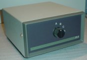
The lack of parallel ports is a common problem in the Amiga community. There is a lot of extra equipment that
is connected to this port. Already in the early days I bought a parallel port switch with four ports. It is
now time to take care of that switch and the stuff that should be connected to it. Originally the switch was
housed in a gray metal box that was screaming "computer part from the early 80's". I have archived that box
and moved the switch to one of the 5.25" slots. The cover is now also where a lot of the switches and
buttons for other small hacks are located.
|
|
|
|
With a few internal parallel ports we can start installing some equipment that would normally be found outside
of the computer. The first one is a small adapter to connect two more joysticks to the Amiga. This is used in
many four player games. I made the adapter long ago so now I just need to place it in one of the ports on the
switch and smile. On the back of the tower case there are two pre-made holes where the two joystick ports can
be placed. The Eagle tower case is very good in this respect.
|
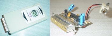
The next thing to place in a parallel port is a sampler. The sampler is a MasterSound, and I remove the case
to make it fit better. I place the audio in connector on the front next to the parallel port switch. To
protect the sampler from shortage I wrap it in a heat-shrink tube.
|
|
 The old PIC programmer was built into a connector cover. |
|
|
Parallel port three is used for a PIC programmer that I've made. It used to be placed on the rear of the
computer, and since it needs 12V that isn't available in the parallel port I have had an extra wire to get
that from the external disk drive connector. Not only did this look awful, it also meant a lot of hasstle
when setaing and removing the PIC circuit in the programmer behind the tower case. I use a drill and a file
to get a rectangular hole in the cover where I can put the socket for the programmer. Since the socket will
be exposed to some jerking and pressure when using it I add some heat glue to attach it.
|
 The PIC programmer gets a new power cable which I connect directly to the power supply. This makes it possible to clean out some of the components. |
|
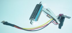
 A parallel port ready for installation. |
|
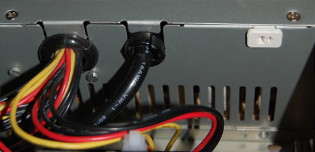
I use a cable to install the last parallel port in the rear of the tower case, where the original Amiga
parallel port used to be. At the same time I connect the now internal parallel port on the Amiga motherboard
to the input of the switch. I wrap the connectors in heat-shrink tubes.
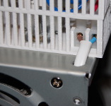
 The internal parallel port is wrapped in a blue heat-shrink tube. The new external port (the red one) is seated in the hole that was left. |
|
The front
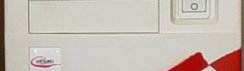
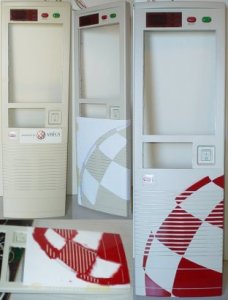 On the left we see the old front. On the right we see the result. |
|
The front of the Eagle tower case is of the old beige kind. In the past I did a desperate attempt
to pimp the front by putting some color on the buttons and add a sticker. The sticker is the only
hint on this case that there is an Amiga inside. I don't have the time, and I don't want to turn
the front of this case into a flashing spacecraft, but maybe some red paint can do some good here.
There are a few wires that needs to get from the front to different parts of the computer. There
are the LEDs on the front, and all the buttons for different extensions and hacks that we have
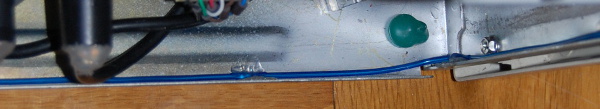
covered so far. To avoid all the wires hanging through the case I put a conduit from the front to
the back of the case.
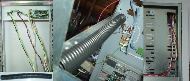 The conduit is placed in a beam in the case. This way it won't consume any additional space. The wires are lead through a (new) hole in the side to get them out of the way for hard drives and other stuff that will be added later. |
|
|
|
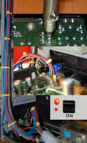
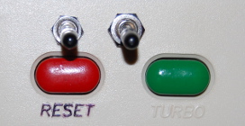
One of the original LEDs in the tower case has been replaced by a double LED. I connect this one to the
turbo button so that it shines green or red depending on the button's status. There are two more builtin
LEDs on the front, I connect these to hard drive activity and power on the motherboard. The three LEDs
that are installed in an Amiga 1200 has builtin resistors. The LEDs that came with the tower case did not.
For this reason I have added resistors on the wires to the LEDs. The original LED for hard drive activity
burned before I realized that resistors are fun, so I have replaced it with a LED with a builtin resistor
(which is why the red wire don't need an external resistor).
|
Things on the front
|
As the front has been put in place it is time to add the accessories that will be seen from the
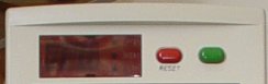
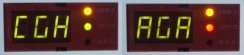
outside. At the top we have the LEDs that we already connected. There is also the good old 3x7
segment display that used to show the processor speed on old PCs. Since it is connected to the
turbo button I find it suitable to have it reflect what happens when one presses the turbo button.
In the image to the right both cases are shown. (Remember that we connected the turbo button to
the BMon.)
|
|
|
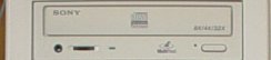
In the first visible 5.25" slot (the actual first one is behind the LEDs) I'll place a CD-RW
manufactured by Sony. I connect the audio connector on the back of the CD to a small mixer that
mixes the audio from the Amiga with the CD sound. We've already seen the mixer, it's built in to
the new audio ports that I never removed from the case at the start of this story.
|
|
|
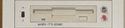
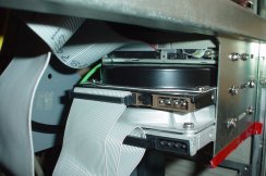
Next we have a floppy disk drive. This is df1: and used to be an external Datic from which I have
removed the case. It's installed in the new internal disk drive connector on the motherboard.
The switch to the right of the drive is connected to the micro switch inside the drive and is
used to enable and disable the write protection of the disk. This switch can help avoiding writing
to or formatting disks by mistake but most often it is used to enable writing on disks that has
been permanently write disabled without having to resort to using tape to cover the hole in the disk.
The red button is used to signal disk change to the Amiga which has to be done for it to notice
that the write protection has changed. To the left of the drive is the drive's on/off button.
|
|
|
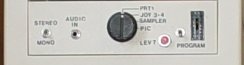
Further down I place the parallel port switch with all the stuff connected to it. Here we can also
see the buttons for level 7 interrupt and mono/stereo sound.
|
|
|
df0: This is the internal disk drive, originally from the Amiga. The cover piece came with the tower case.
Behind the transparent plastic I have attached a LED that is connected to floppy activity on
the motherboard.
|
|
|
Update 2018-01-02:
Technology advances every day, at the same time as the floppy disks get more difficult to read. To save
as much information as possible form the floppies, I transfer them to ADF files and replace df0 with a Gotek floppy
drive emulator which reads the ADF files from a USB memory. df1, of course, remains so that I can read regular
disks too.
|
|
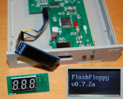
Update 2018-07-18:
The Gotek display only hosts three digits. This limits the amout of information that can be
displayed. Luckily the drivers do have support for a 128x32 OLED display and replacing the
display is relatively painless. Some plastic in the Gotek case had to be removed since the
new display is larger than the old one. I use heat glue to attach the new display.
|
|
|
|
Behind this part of the front I install two hard dirves. No, they are not visible from the outside but I'll install
them now anyway. There is one Conner 600 MB and one Fujitsu 3 GB. I have for some time planned to get a
new and bigger and most importantly quieter hard drive, but since I have a separate file server at home
I haven't been able to fill the hard drives I have now. AmigaOS 3.9 doesn't require a lot of space...
|
|
|
|
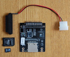
Update 2015-02-24:
Filling a hard drive is just a matter of time, and a question of how many floppys one want to have
next to the computer. The hard drives are now 98% full and it was time to do something. Just
replacing them with a larger hard disk is boring and not very future proof since IDE disks are
not available through normal stores any longer. Instead I buy an IDE adapter for SD cards. The
adapter has an adapter to enable installation on the larger (3.5") type of IDE connector,
and in the adapter I place an adapter to install a smaller SD card. The SD card capacity is 8 GB.
|
Using some screws, plates, and a rubber mat to protect from shortages I install the SD card reader
on the side of the hard drive frame.
I remove the Conner disk that sounds like a jet engine and use the SD card as the boot drive. The
first thing I do in the startup-sequence is to cut the power to the Fujitsu drive that now acts as
a backup. Booting from the SD card is faster than using a harddrive and obviously completely quiet.
|
|
|
Update 2018-07-25:
The cables that consumed the most space inside the case was the old ribbon cables for the harddrives and the CD.
I've finally gotten around to replace these with round ribbon cables.
|
|
Power supply
|
|
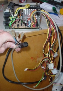
The power supply unit (PSU) has also been exposed to some modifications (of course). There were
too few power connectors in there to cover all the additional hardware I have installed, and I
needed a custom cable to the motherboard. (I got some extra wires and connectors from a different
PSU.)
The power connector to the motherboard requires other voltages than +5V and +12V that is found in
the red and yellow wires from a normal PSU. Luckily so does a PC motherboard, so the required
-12V was available in the PSU.
The power button is located on the front of the computer. To make it possible to hide the cable
between the button and the PSU I make it longer that it originally was.
|
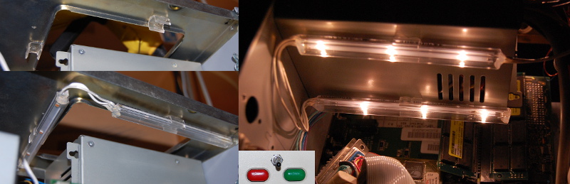
Let there be light
|
|
Parts of the tower case is getting pretty full by now, and dark. Outside light can't get all the way in to
the motherboard, especially not on the darker hours of the day. To fix this I install some work light
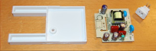
in the case. I found these LED lights on IKEA and they suit me well since they give plenty of light without
emitting any noticeable heat. In the box I get three LED sticks with wires and a power adapter.
The LED lights use 24V so it would be possible to take the power from the existing PSU, but that would
mean that the lights could only be lit when the computer is turned on. Most often when messing around in
the computer it helps to have the power off. The power adapter that came with the lights is obviously
perfect for the job, but I don't have any extra power socket inside the computer. As I need real current
(240V) I will need to get it from within the PSU. For safety reasons I will not bring out high voltage
current outside the PSU, so I'll have to place another power converter inside the PSU.
Warning!
If you are like me you may have read the warning at the beginning of this story and thought "that's fine
I have seen a soldering iron before, what could possibly go wrong?" Most of the time this is a perfectly
fine attitude, and as long as it doesn't matter if you break something, just do it! BUT, what we are about
to do now is dangerous for real. If something goes wrong here it won't just break the computer. It could
kill you! Don't do this unless you are experienced with high voltage installations. Make sure you have
a working ground breaker and pull the plug to the computer again!
|
|
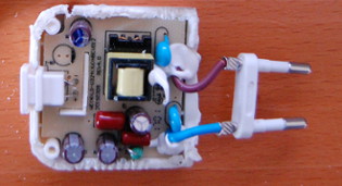
I'll start by cleaning out all the unnecessary plastic from the power adapter. It's not made to be opened
so I use a saw, as carefully as possible not to damage the content. Finally I can extract the circuit board
and loosen the LED connector. The connector will be placed in the PSU casing while the circuit board will
need to be placed somewhere where there is some free space. The only place where there is space enough
is in mid air, so I build a frame that can hold the card in place and attach it to the side of the PSU.
I also cut out a hole in the PSU for the connector.
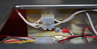
The power plug is replaced with a couple of wires that I connect to the incoming power connector. I
connect the LED connector and screws everything in place. I don't want anything to fall out of place inside
the PSU. Once everything is in place I close the lid. The only trace of this hack is now the small
white connector on the outside.
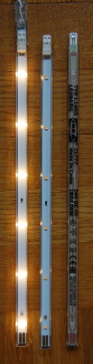
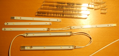
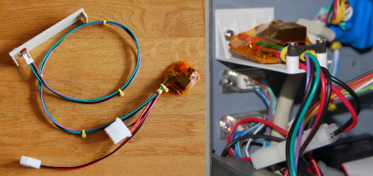
It's time for the actual lights. The LED sticks are designed to be installed in a single row with connectors
in the ends to join the three pieces into one. To spread the light inside the computer I'll need to place the
lights in a few different places, and as it turns out, even one of the three sticks are too long to fit where
I want to place them. I cut each of the thin circuit boards with the LEDs in two pieces. The plastic casing
requires a saw to divide. Then I reuse the wire that came with the lights to connect the pieces two by two.
A close look at the circuit board shows that the three sticks were actually connected in parallel, so they don't
need to be all three in a row. That suits me perfect. I make three lines with two circuitboard pieces in each
that I connect to a terminal strip that is placed in the top of the tower.
The LED lights came with clamps that I glue in place in a few selected locations. Then I simply place the LEDs
in the clamps. The clamps make it very convenient since I can easily remove the LEDs and use them as a hand-held
flashlight in case I need extra light somewhere. I do try to spread them out though so that it shouldn't come to
that. One of the lines is placed at the very top of the tower case, the second in placed below the PSU, and the
third I place with one part on the lower front and the other part below the network adapter.
Finally I add a switch between the terminal strip and the power connector and hook it all up. The switch is
placed at the very top of the case. It's starting to get crowded on the front of this computer...
|
|

 My first tower. |
|
As I have hinted a few times there is something more that is going into this tower case, something
that will require more space that any expansion we have seen so far. I have saved the bottom part of
the case for this. What I'm installing now is a different machine that has been with me for a long time,
even longer than the Amiga actually. A Commodore 64.
This C64 is used to be installed in a tower case as it has been that way since the early 90's, so I don't
think it will notice anything. The earlier tower case was a merge of my first and second C64. The
first one died after a short in the joystick port so that motherboard ended up as a decoration on the
wall. The empty case was cut up to become the casing for the keyboard. Today I regret that I didn't
keep the old case for the computer and used the new one for the keyboard, but at this point it doesn't
matter any more. The logotype that can be seen in the header of this section is moved from the
original case to the new home of the C64.
The wires between the keyboard and the computer mainly consists of the keyboard stuff, but there are
a few extra wires for the reset button, the LED, and a freeze button.
|
 On the rear we now find the joystick ports and the power switch for the C64. |
|
The C64 motherboard, assy 250469, is placed at the bottom of the case. I've already cut another hole in the rear
where I'll place the side of the C64 with the ports. I drill a few holes in the bottom of the case
and mounts the motherboard using metal spacers. The spacers and the metal case itself connects the
ground planes of the two computers in the case.
|
 Another motherboard installed in the tower - or is this the grandmaboard? I was lucky to buy a newer model of the C64 the second time, C64C rev 4 - assy 250469 - the short board. The motherboard of the old C64 was a lot larger and would not have fit in the case. |
Another keyboard interface
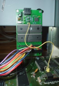 A pice of magical hardware. |
|
Maybe I should use the C64 keyboard out of pure nostalgia, but for different reasons I'll use a
standard keyboard. This may come as a surprise to some, but there is actually PC keyboard interfaces
for the C64 as well. The interface is called PC-KEYB,
and is made by Tomas Pribyl who has several exciting projects to
keep the C64 alive.
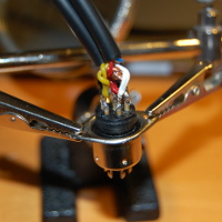
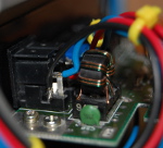
The yellow wire is used for the reset signal so that the C64 can be restarted using CTRL+ALT+DEL.
The pin I connect it to has been there for many years since I already had a reset button in the C64.
|
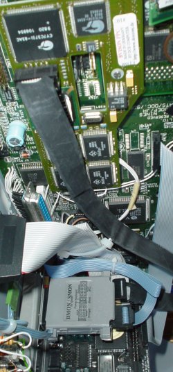
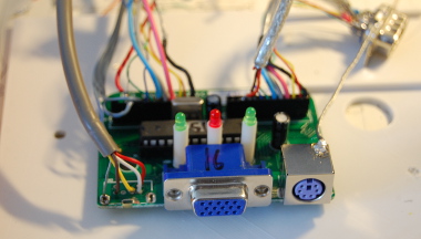
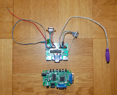
KVM switch
|
In order to use the same keyboard for the C64 as I use to the Amiga, another piece of hardware is
required - a switch to choose which computer the keyboard is connected to. For this purpose I have
found a Hama KVM switch for VGA and PS/2. K in KVM means Keyboard, and I install the switch between
the computers and the keyboard.
V is for Video, and surely it would be nice to also use the same monitor for both computers. BMon
that I use in the Amiga gives me a VGA signal that is compatible with the switch. The C64 video
output is something else though. The video connector on the back of the C64 gives an S-video signal
with the proper resistance, so I get myself an S-video to VGA adapter.
I'm happy with this, but the switch is not. M in KVM is short for Mouse and it turns out that the
switch will not work without one connected. Nor the Amiga or the C64 has any use for a PS/2 mouse
so some investigation work is required. It turns out that it doesn't have to be a mouse, but any
device that can handle the PS/2 handshaking will do.
|
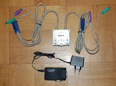 Above, the KVM switch and below it the VGA adapter. |
|
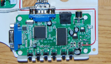
 The same KVM switch and VGA adapter as before, but with less plastic and cables. |
|
Originally the KVM switch has very long cables. This has to be adjusted since all of this is going
in to the tower case. I'll cut up both switch and VGA adapter and keep only the necessary parts.
The cables are cut and I clean the connectors from their casing. I must admit that the connectors
were very stable with hard metal shielding and all, but eventually I could solder the shorter wires
in place. One of the keyboard cables are reused to connect to the C64 keyboard interface. The
Amiga keyboard connector was earlier installed at the back of the computer, but now the KVM switch
will supply the external keyboard connector and the connection to the Amiga is moved into the case.
The old keyboard connector is removed and I solder the Amiga keyboard interface directly to the
KVM switch (the blue flat cable to the left in the picture).
The Amiga VGA connector (on the BMon) must also move into the case and connect to the KVM switch.
And then there was that detail with the PS/2 handshake for the mouse connector. Since I don't have
a PS/2 mouse to place in the Amiga I use the logic from a keyboard. In total there are now four
small circuit boards to install to make this work.
|
|
I start with a paper sketch to find a good layout. The starting point is the cover plate that used
to host the BMon. It will now hold the KVM switch in place. Once I have a decent design I draw it
out as a 3D model and print it.
To connect the card that will perform the PS/2 handshake I remove the mouse port from the KVM switch.
I add a few extra shield/ground wires to connect all the circuits to the computer ground. Also VCC
(+5V) is connected between the cards and directly to a power connector from the PSU. The VGA adapter
used to have its own power supply but as it was only using +5V I discard it and use +5V from the
computer instead (the red wire in the picture below).
Now for the S-video signal from the C64. Using a resistor to adjust the signal we get S-video from the
C64 monitor port.
(More
about the details here.) Since there is not enough space by the connector I use heat glue to insulate
and bend the cable upwards.
|
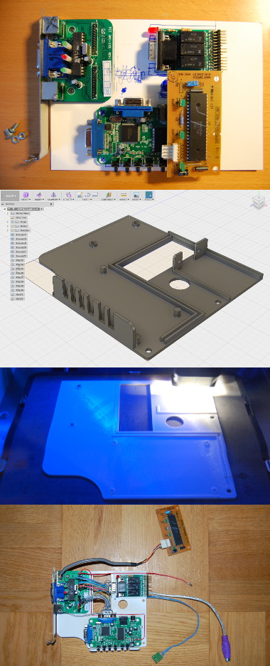 With some help from the 3D printer I manufacture a bottom plate to put the circuits on. |
|
I drill a hole for the keyboard connector in the cover plate and finally the switch is installed in the
computer. I reused the sticker from the side of the VGA adapter to keep track of the buttons on the
adapter. I don't expect to use these buttons but if that turns out to be necessary I'll bring them
to the front of the computer.
Update 2017-10-08:
The video coord to the C64 turned out to be too short to be able to hide it nicely. I have replaced it
with a slightly longer cable.
The Final Cartridge III
|
A C64 requires a cartridge. I the days where I used my C64 the most I had an Action Replay VI. For
some stupid reason I sold it a few years later. I still have my older cartridge, The Final Cartridge III,
and obviously I want to install it in the expansion port. Unfortunately there is no space around the
C64 motherboard so in order to have something in the expansion port I need to turn it upwards.
There is some work involved. First I need to remove the shield plate. Then I can heat up the inner row
of the port pins and pull them out. Using a small drill I clean out the row of holes and then I put the
legs back and bend the entire port upwards. I fixate the pins with solder and cut the pins that sticks
out beneath the motherboard. Now I can put the TFC III in place.
|
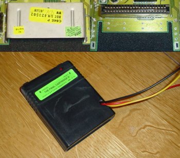 On the right of the TFC III there are three wires coming out. These I'll pull up to the front of the tower to connect buttons for freeze, reset, and the LED that indicates if TFC III is active or not. In the upper part of the picture we see the expansion port before and after the operation. |
|
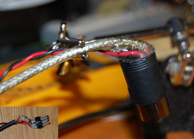
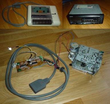
A tape recorder
|
|
If I am to use my C64 I guess I better have a tape recorder as well. The tape recorders I have for
the C64 will not allow themselves to be installed in a tower case without a fight. It's time to bring out
the toolbox again. In the junk yard I bought a car stereo for five bucks. The mechanics from that together
with the electronics from the C64 datasette is now to be merged. Using my trusty side cutter I clean out
all the unnecessary parts from both devices. I keep the motor and the recorder head from the car stereo
since it would mean too much work to move them from the datasette. Unfortunately this means that I can no
longer save stuff on tape.
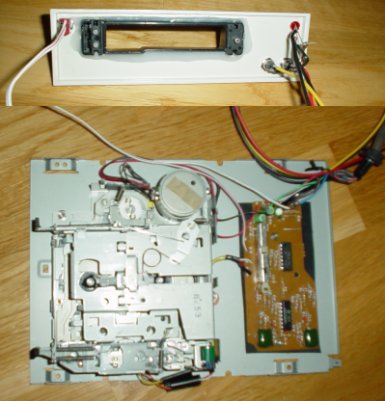
The car stereo has buttons to fast forward and reverse, and to eject the tape. It don't however have a
button for PLAY since this used to be controlled by the electronics in the car. An electro magnet
controls if the player head is to be pushed to the tape or not, and the motor is connected to the
electronics in the car stereo. This part of the car stereo is gone now and I connect the motor directly
to the datasette's electronics.
At first I tried to connect the electro magnet directly to the motor signal thinking that the player
head would push towards the tape when the motor was running. This didn't work out though since the
tape started moving before the head got in touch with it. Some data on the tape was missed and resulted
in some games not working. Instead I cut the player head loose from the control circuit and have it
lay against the tape at all times. I can put any concerns to rest by ensuring that there is other
mechanics in the stereo that removes the head from the tape when fast forwarding, reversing or ejecting
the tape. For the PLAY signal itself the motor signal in the datasette can not be trusted. The motor
in a datasette is often running even though PLAY is not pressed. Instead I use a separate switch for PLAY.
The separate parts are assembled inside the cover from a CD player. Using this I can install the new tape
recorder in the tower case. I need a front panel as well. I cut up a hole in the front panel for the tape
slot. I have cut out the plastic from the car stereo front with the tape slot to bring over the buttons
and the slot itself where the tape is to be inserted. I use heat glue to put these in place.
The tape mechanics was raised somewhat with spacers and underneath the circuit board i use a rubber mat
to avoid shortages. I mount the front panel in the CD cover using heat glue. I also use this front panel
to place all the buttons and LEDs related to the C64. Finally I put the lid on and install the package into
the computer.
Obviously there is more to do with the C64, but that will have to wait for a later occasion.
|
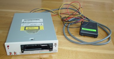
Serial port
|
The C64 serial port will host among other things a 1541-II disk drive. Since the 1541-II is a valuable
piece of vintage hardware today I will not take it apart to install it internally in the tower case. Instead
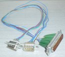
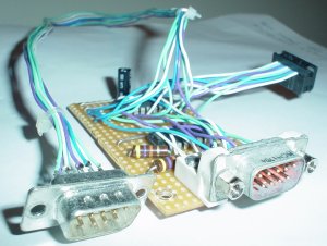
I will move the serial port to the back of the case. To prepare for a future project I will also need an
internal serial port, so I'll make a Y cable.
I place the male connector in a female when soldering. This gives increased stability and helps keep the pins in
place. Since I have to cut the connector to get it to fit in the case I use heat glue to build a new rear of the
connector with an angle pointing downwards.
|
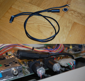 The serial Y-cable. Since the external connector should be mounted from the outside of the case, I need to pull the wires through the hole in the case before soldering it in place. |
|
Recaping
|
|
My C64 celebrated 30 years this year and several people have told me that it is due for a "recap" - that
means replacing all electrolytic capacitors on the motherboard. Not much to say about that, some soldering
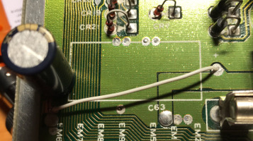
later all the capacitors are replaced. Unfortunately my default store did not carry axial 1000uF capacitors,
so I had to use a radial one for C63. Only after I had put it in place and cut the reminder of the leads
underneath the circuit board I realized that I should have tilted it 90 degrees to fit the marks on the
motherboard...
To attach C63 easily i use two terminals placed on the ground plane next to the capacitor. I grind the copper
away to isolate the two terminals from ground and solder the positive side of the capacitor there. Then I
use a small wire to attach the capacitor to the terminal where the lead used to be.
|
Internal power
 My first C64 power supply. |
|
A well known problem with the power suplies that came with the C64 is that after all these years the +5V
line might output a higher current. This might damage the C64. My first C64 power supply unit retired years
ago. In its golden age it was powered on around the clock for periods of several months. The heat emitted
from the unit caused the plastic cover to melt in a few places and eventually it was a danger to itself and
anyone nearby. My second C64 came with a more modern power supply unit which has survived all the way till
today. There is currently nothing wrong with the +5V in it, so my main motivation to this exercise is that
I simply don't want an external PSU when I already have one internal.
|
|
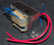
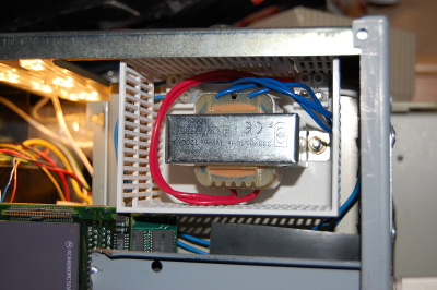
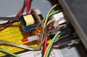
The internal PSU that until now has solely been used for the Amiga is delivering a solid +5V DC, but the C64
also want 9V AC. For this I will need a new transformer. The PSU case is crowded so this new 9V transformer must
be located outside of it. It will consume 230V AC so to reduce the risk of electric shock I print a small cage
using the 3D printer. In the cage I make holders for terminals to ease the installation. The cage is attached to
the side of the PSU.
|
|
As on the Amiga I attach the power cables on the back of the power connector on the C64 motherboard. The power
will thereby enter the motherboard the same way as before, which means that the old power switch will continue to work as before.
|
|
|
|
I get the 230V AC from the circuit board inside the PSU. I attach the cable after the fuse to allow the
new transformer to enjoy some safety as well. To clarify: I don't get the power directly from the
incoming power as I did with the work light. This means that the PSU must be turned on to get the 9V AC.
On the other hand the PSU must be turned on to get the +5V DC as well, so I don't see this as a problem
even though it means that the Amiga will always be on when the C64 is to be used. The way the computer is
built with the KVM switch etc. this is already a requirement for everything to work anyway. The C64 still
has its internal power switch of course, so it won't boot up every time the PSU is turned on.
|
|
Power switch
|
|
With the C64 placed the way it is, at the bottom of the case, with power and joystick connectors at the
rear, the power switch ends up being hard to reach. To make it more practical I need to move the switch
to the front of the computer.
I start by desoldering the leads on the power switch and clear the surface where it used to be located.
As I got some criticism over the parallel port incident in the Amiga, I have now acquired a proper desoldering iron.
Removing the power switch leads was very easy now. The power switch is still attached to the motherboard
at the front of the switch. I leave this solder joint in place so that the switch can stay where it is.
Even though the switch won't be connected, I want it there for the aesthetics of it, and to avoid an open
hole into the computer.
Instead of the switch leads I solder four wires in place that I bring all the way up to the front where I
connect them to a different power switch from a C64 that I keep around for spare parts.
|
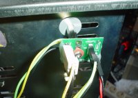
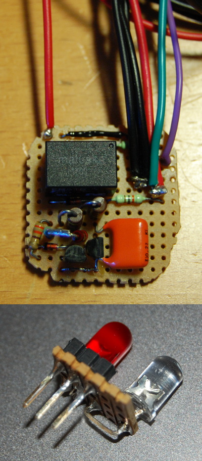
Overvoltage protectionOriginal design: C64 Saver | 2018-07-18 |
|
Many old C64 power supplies are giving up and there is a risk that the +5V increases to levels
that can damage the electronics in the computer. I've already replaced the old power supply for
a newer one, but that doesn't mean that the new power supply is new. Regardless of the age of
the power supply I don't want the C64 to get a chock, so I'll build an overvoltage protector.
The overvoltage protector is based around a zener diode and two transistors that drive a relay.
If the voltage is too high the relay will cut the power and save the computer. I'll solder all
the parts together and put some connectors on incoming and outgoing power. Two LEDs show if
everything is OK or if the relay has killed the power. The original design also had a LED to
show that the 9V is OK. I haven't built that part yet.
I print a holder for the circuit board. The holder will also act as a cover for the hole where the
old keyboard connector was seated before the KVM switch. I wrap the circuit board in a heat-shrink
tube to avoid shortage. Finally, I place the LEDs on the front next to the main power switch.
|
|
The cover
The airflow in this tower case enters the case through a vent bar in the lower part of the front and
is blown out through the PSU in the top rear. It passes by most of the parts in the case now, but not all.
One part that could really need some venting is the PPC processor. It is turned the wrong way to get any
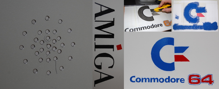
air flow. For this purpose I drill a few extra air holes in the cover next to it.
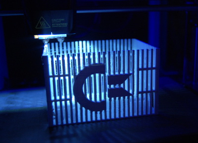
To make it obvious what this machine is I add an Amiga logo on the side of the cover.
Update 2017-08-31:
As there is also a C64 in the case these days I think it is only fair that there is a C64 logo on there
as well. I copy the text from the original box and cut out a template. Add some paint and it's all done.
|
|
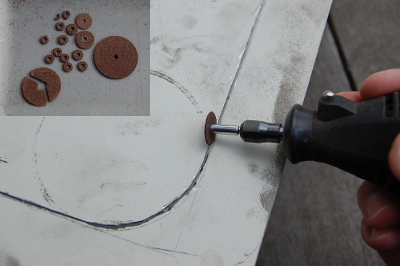
Update 2017-08-20:
The work on this computer has been done in several parts over many years. Each time I have to open the
computer I need to disconnect everything to bring it out from its place under my desk since the cover
needs to be pulled back and up to be removed. To make future work easier I'll cut out a service hatch
in the side.
Using a Dremel I cut away most of the side. In retrospect the Dremel may not have been the best tool
for the job. Everything went well but it did require 16 heavy-duty cutting wheels. The edges are filed and
grinded to get rounded and non-sharp and I drill holes in the corners to be able to add a hatch.
|
|
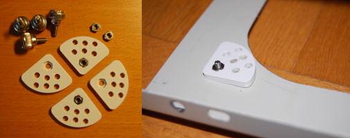
For the hatch I use screws with big heads to make it easy to remove them without tools. I print four
holders for the nuts so that I can hold them in place on the inside. I put them in place using heat glue.
The holders have a number of holes to allow the glue to get a better grip.
With all the stuff in this tower case there are now more LEDs inside the case than there is on the outside.
Kind of wasted one could say. Therefore I make the hatch out of plexiglass so that the contents of the case
can be seen even when the cover is in place.
|
|
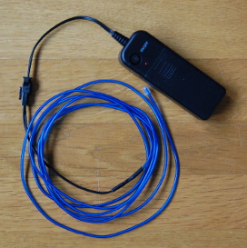
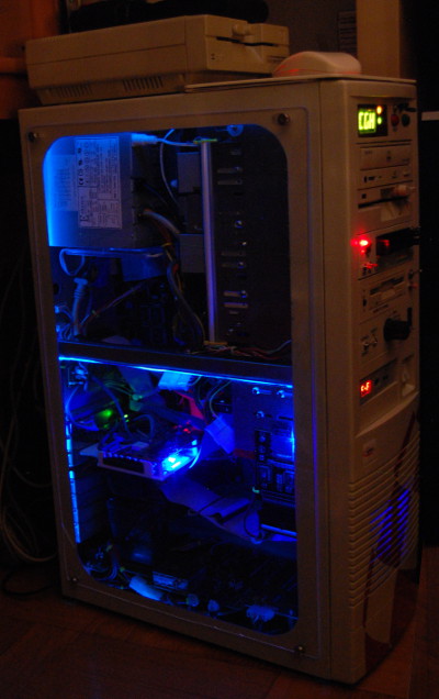
Ambient light
|
|
With the new window into the computer it would be nice with some kind of decorative light in there.
I found a light tube with a subtle blue light that I hope will do the trick. The tube uses batteries, 3V,
and has a small control circuit that makes it shine and blink. I don't want any blinking so the control
circuit isn't really needed. At first I planned to just throw the circuit away but since the tube uses
430V AC and the transformer and other control logic is on the board as well, I'll keep it as is and
simply short the control signal from the IC (that is active low) to ground to make the tube lit constantly.
|
I use a 3V voltage regulator to bring down the 5V from the computer. I take the current from the BMon circuit
that is placed at the top of the tower case. I also attach the new circuit board to the BMon circuit using a few
spacers. I use a switch to cut the current to be able to turn the light on and off. The switch is placed at the
top of the front, next to the other light switch.
I attach the tube with heat glue around the edge of the case.
|
|
|
Development
2005-06-03:
2010-01-16:
2017-08-23:
2017-09-16:
Uppdatering 2017-10-08:
The initial goal of this project was to clean up in the tower case. Over time a lot of new hardware have
been added and this goal has slowly been forgotten until a friendly soul who read this page pointed out
that there isn't more air flow in the tower after all. I decided to clean up the wiring again.
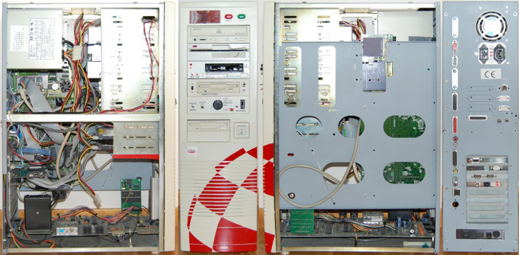
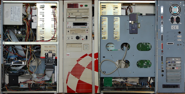
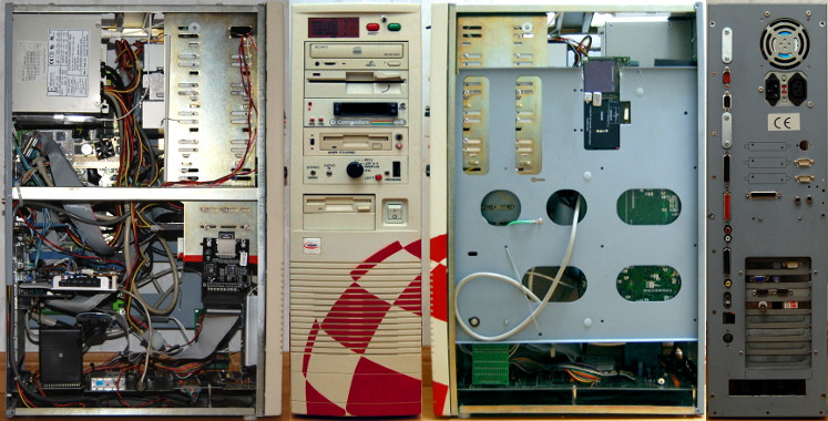
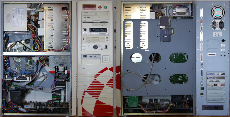
A result
Looking back at how I started out in 2005, I did get rid of some of the cabling inside the computer, but now there is
more hardware in the case instead.
|
Through the top we mainly see the PSUs, the CD drive, some cabling, and the driver cirquit for the ambient light.
Through the sides (below) we see a lot more.
|
|
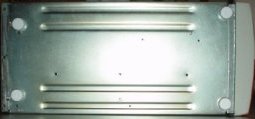
Since I now have screws through the bottom I had to add some pads under the computer in order to
save the floor from scratches. The pads are made to be nailed into wooden furniture. I put them in
drilled holes using heat glue on the inside to keep them in place. Yes, I know, the two rear pads are
not aligned. I couldn't drill a hole where I wanted to, there was a computer in the way...
|
|
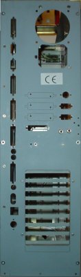
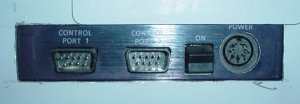
On the back we can now see
all the external connectors. Some of the holes that was used before is no longer needed since for instance
the external disk drive has been moved inside the case. These are covered with metal pieces.
On the right, below the PSU, joystick ports 3 and 4 are located. Beneath those the new audio outputs. In the
middle, next to the audio, we find the parallel port that came with Hypercom 3+.
In the top expansion card slot we find joystick port 1 (from the mouse/joystick switch). Then we have the
KVM switch with a VGA and keyboard connector. The third slot houses the Hypercom 3+ with its serial ports,
and number four is the network connectors.
At the bottom we find the original side from the C64 with two joystick ports, the power switch which is a
dummy at this point, and the power connector. Slightly above to the left, below the square Amiga power connector,
we find the C64 serial port.
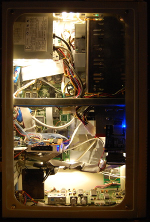
The cover in place
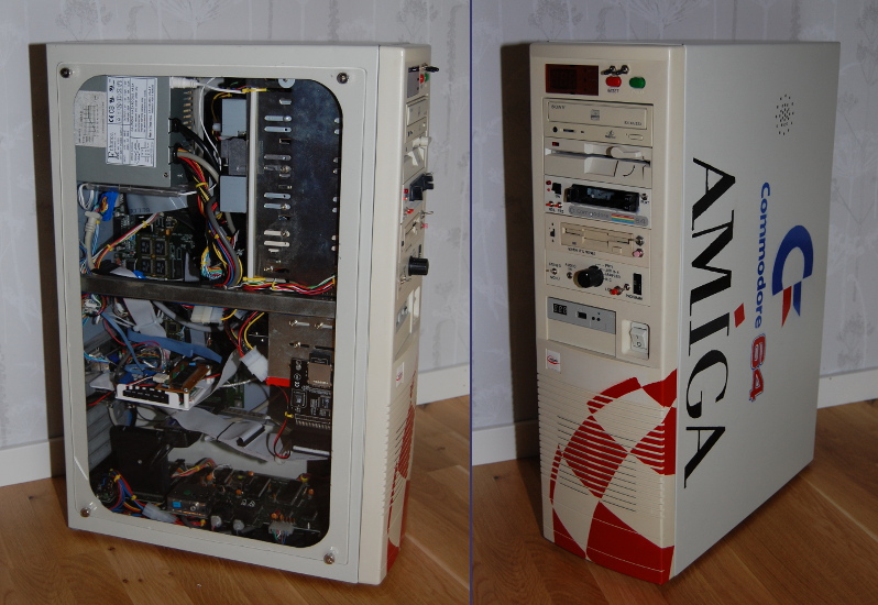 This is the final result for this time. New things are added all the time so this picture is not necessarily showing the latest version. |
|
That's it for this time. I do have several more projects left that I haven't gotten to yet.
Some are small things that I hope to get to fairly soon, some are larger projects that will
require more time. Please return to this page sometime in the future to see if anything more
has happened. :-) Until everything is done I can only say:
To be continued...
|
 Hooked up and ready to go. |
|
Back to index |

 Svenska